Japonský architektonický institut (AIJ) představil řadu známých srovnávacích scénářů simulace větru.
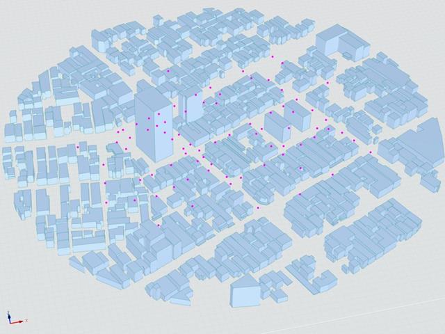
V následujícím příspěvku se budeme zabývat případem E - komplex budov ve skutečné městské oblasti s hustou koncentrací nízkopodlažních budov ve městě Niigata.
V následujícím textu je popsaný scénář simulován v programu RWIND2 a výsledky jsou porovnány se simulovanými a experimentálními výsledky AIJ.
Japonský architektonický institut (AIJ) v souladu se srovnávacími testy pro Windsimulation vorgestellt.
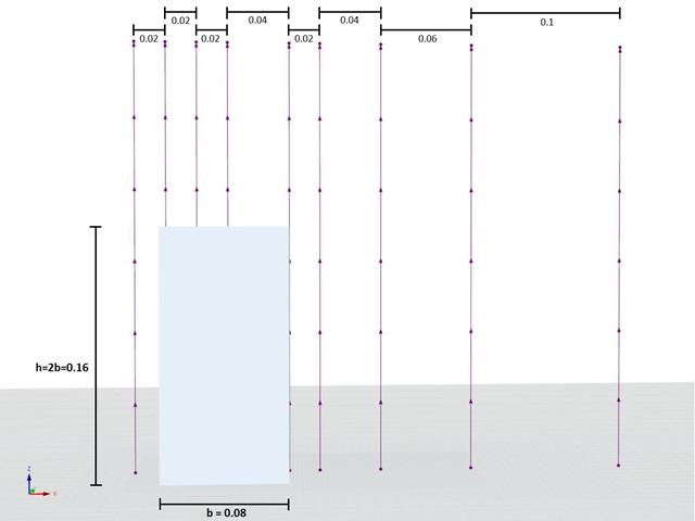
Podle nového návrhu "Případ A - výšková budova ve tvaru 2:1:1".
Im Folgenden wird das beschriebene Szenario in RWIND2 nachgebildet and die Ergebnisse se simulierten and der experimentellen Resultate des AIJ verglichen.
Japonský architektonický institut (AIJ) představil řadu známých srovnávacích scénářů simulace větru.
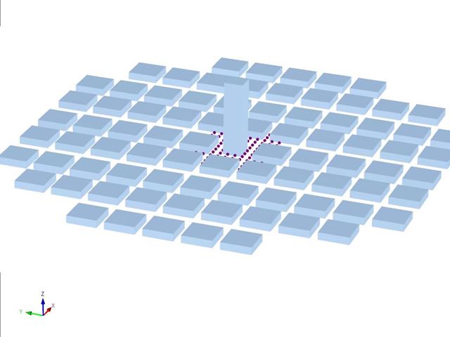
Následující článek se zabývá případem D - Výšková budova mezi městskými bloky.
V následujícím textu je popsaný scénář simulován v programu RWIND2 a výsledky jsou porovnány se simulovanými a experimentálními výsledky AIJ.
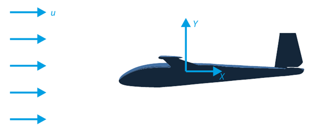
Cílem tohoto verifikačního příkladu je analyzovat proudění okolo kluzáku. Úkolem je stanovit součinitele odporu vzduchu a součinitele vztlaku vzhledem k úhlu náběhu. Pro tyto součinitele lze také vykreslit aerodynamickou poláru. Z pole rychlostí lze také určit mezní úhel laminárního proudění okolo profilu křídla. V programu RWIND 2 se použije dostupný 3D CAD model (soubor STL).
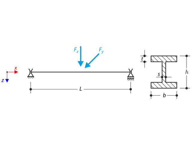
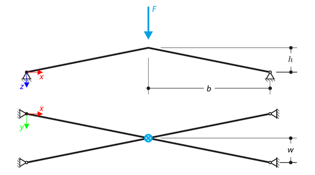
Konstrukce z I-profilu je vetknuta do vidlic. The axial rotation is restricted on both ends while warping is enabled. The structure is loaded by two transverse forces in the middle. The verification example is based on the example introduced by Gensichen and Lumpe.
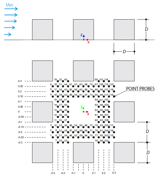
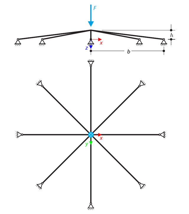
Verifikační příklad popisuje zatížení větrem v několika směrech proudění větru na modelu skupiny budov. The model consists of eight cubes. The velocity fields obtained by the RWIND simulation are compared with the measured values from the experiment. The experimental data are measured using a thermistor anemometer in the wind tunnel.
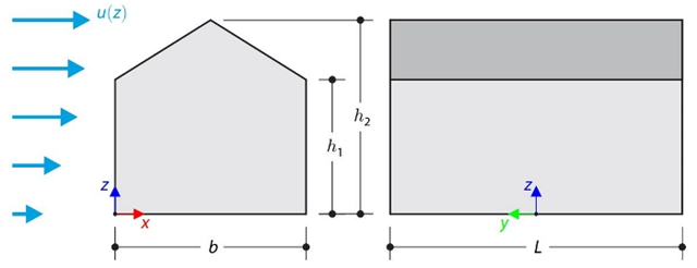
This verification example compares wind load calculations on a duopitch roof building using the ASCE 7-16 standard and using CFD simulation in RWIND Simulation. Budova je zadána v souladu s náčrtem. Rychlostní profil proudění vzduchu byl definován podle normy ASCE 7-16.
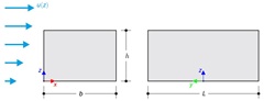
This verification example compares wind load calculations on a flat roof building using the ASCE 7-16 standard and using CFD simulation in RWIND Simulation. Budova je zadána v souladu s náčrtem. Rychlostní profil proudění vzduchu byl definován podle normy ASCE 7-16.
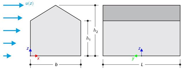
Verifikační příklad porovnává výpočet zatížení větrem na budovu se sedlovou střechou podle normy EN 1991-1-4 a pomocí CFD simulace v programu RWIND Simulation. The building is defined according to the sketch, and the inflow velocity profile is taken according to the standard EN 1991-1-4.
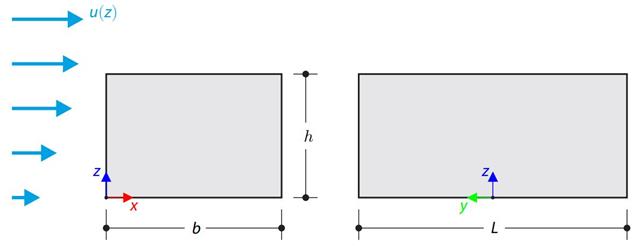
Verifikační příklad porovnává výpočet zatížení větrem na budovu s plochou střechou podle normy EN 1991-1-4 a pomocí CFD simulace v programu RWIND Simulation. The building is defined according to the sketch, and the inflow velocity profile is taken according to the standard EN 1991-1-4.
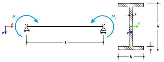
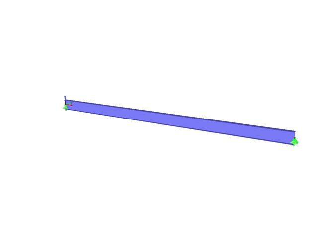
A simply supported beam is loaded by pure bending. Stanovíme kritické zatížení a příslušný součinitel zatížení od boulení.
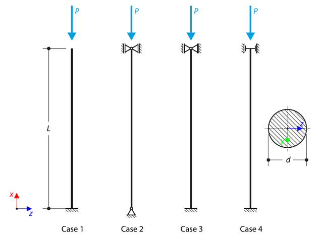
Dialog s kruhovým průřezem je podepřen podle čtyř základních případů Eulerova vzpěru a vystaven tlakové síle. Determine the critical load.
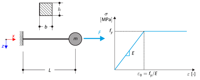
Tento verifikační příklad vychází z verifikačního příkladu 0122. A single-mass system without damping is subjected to an axial loading force. An ideal elastic-plastic material with characteristics is assumed. Determine the time course of the end-point deflection, velocity, and acceleration.
A symmetrical shallow structure is made of eight equal truss members, which are embedded into hinge supports. The structure is loaded by a concentrated force and alternatively by imposed nodal deformation over the critical limit point when the snap-through occurs. Imposed nodal deformation is used in RFEM 5 and RSTAB 8 to obtain the full equilibrium path of the snap-through. Vlastní tíha se v tomto příkladu nezohledňuje. Determine the relationship between the actual loading force and the deflection, considering large deformation analysis. Evaluate the load factor at the given deflections.
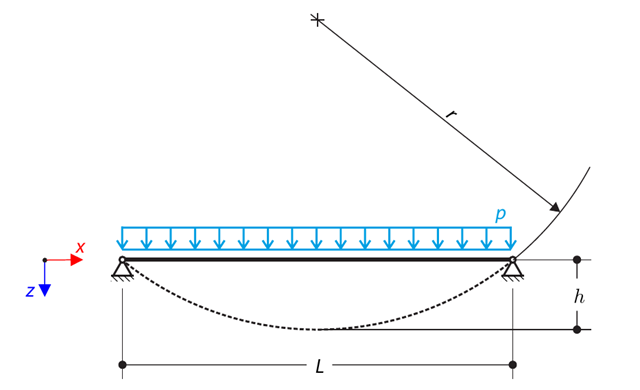
A cable is loaded by means of a uniform load. Výsledkem je deformovaný tvar kruhového segmentu. Determine the equilibrium force of the cable to obtain the given sag of the cable. The add-on module RF-FORM-FINDING is used for this purpose. Elastic deformations are neglected both in RF-FORM-FINDING and in the analytical solution; self-weight is also neglected in this example.
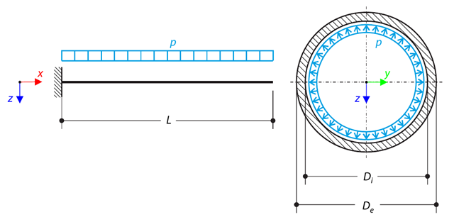
A pipe with a tubular cross-section is loaded by internal pressure. This internal pressure causes axial deformation of the pipe (the Bourdon effect). Stanovte axiální deformaci koncového bodu trubky.
Konstrukce se skládá ze čtyř prutů, které jsou uloženy na kloubových podporách. The structure is loaded by a concentrated force and alternatively by imposed nodal deformation over the critical limit point, when snap-through occurs. Imposed nodal deformation is used in RFEM 5 and RSTAB 8 to obtain the full equilibrium path of the snap-through. The self-weight is neglected in this example. Determine the relationship between the actual loading force and the deflection, considering large deformation analysis. Evaluate the load factor at given deflections.
Consider an ASTM A992 W 18×50 beam forspan and uniform dead and live loads as shown in Figure 1. Maximální jmenovitá výška prutu je 18 palců. The live load deflection is limited to L/360. The beam is simply supported and continuously braced. Verify the available flexural strength of the selected beam, based on LRFD and ASD.
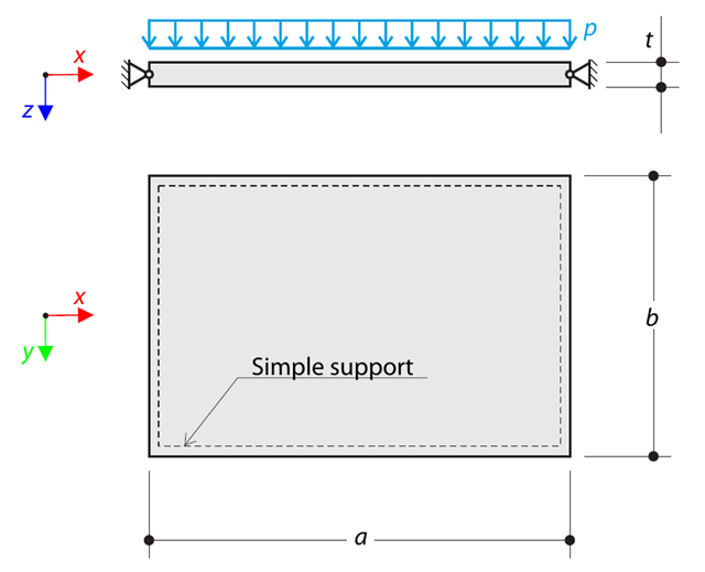
A thin rectangular orthotropic plate is simply supported and loaded by uniformly distributed pressure. The directions of axes x and y coincide with the principal directions. Maximální průhyb desky se stanoví bez zohlednění vlastní tíhy.
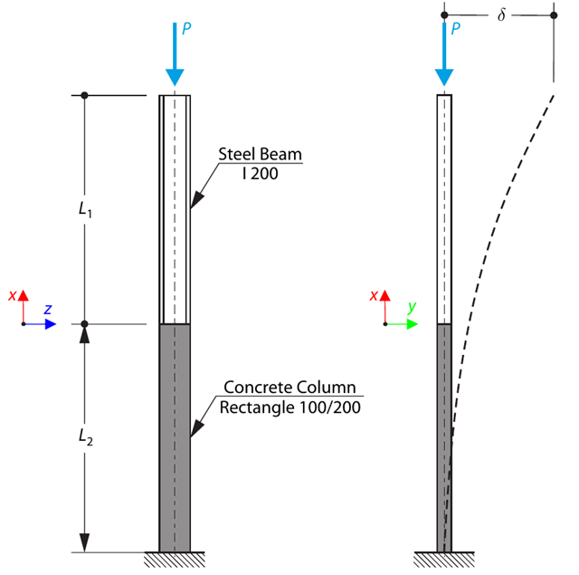
A column is composed of a concrete section (rectangle 100/200) and a steel section (profile I 200). Je vystaven tlakové síle. Determine the critical load and corresponding load factor. The theoretical solution is based on the buckling of a simple beam. In this case, two regions have to be taken into account due to different moments of inertia and material properties.